
Development Scrapbook
CRISM was selected by NASA in Novermber 2001 for flight on MRO. It was chosen by a competitive process in which universities and industry submitted proposals for a visible-infrared imaging spectrometer, and one was selected by an impartial panel of scientists and engineers. This is the story of how a spacecraft instrument goes from an idea to exploring the solar system.
1
 Before NASA selected CRISM to fly, a small group of scientists and engineers
spent a year identifying how the instrument needed to work, and coming up with the
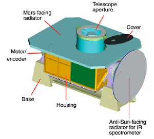
conceptual design shown here. Much of the inspiration for the design
came from the imaging system on the MESSENGER mission to Mercury.
This design was not meant to be final but instead to show that
CRISM could be built. Less than 1 person-year was spent on the
conceptual design. Later, once
CRISM was selected, over 140 person-years were spent refining the
design and building and testing the instrument.
Before NASA selected CRISM to fly, a small group of scientists and engineers
spent a year identifying how the instrument needed to work, and coming up with the
conceptual design shown here. Much of the inspiration for the design
came from the imaging system on the MESSENGER mission to Mercury.
This design was not meant to be final but instead to show that
CRISM could be built. Less than 1 person-year was spent on the
conceptual design. Later, once
CRISM was selected, over 140 person-years were spent refining the
design and building and testing the instrument.
2
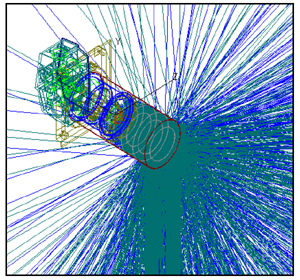 During 2002 a detailed design was developed and analyzed, step by step. The detailed design turned a concept into drawings that could be used to build hardware. The design was iterated as analysis of its expected performance got more complete. At left is some of the analysis of scattered light that was used to derive the exact dimensions for the telescope baffle that would block sources of stray light from outside the field of view.
3
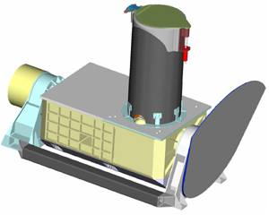 By 2003, the design had stabilized. A computer-assisted rendering of the OSU as of early 2003 is shown at left. Each of the more than 400 parts in CRISM had its own detailed design, which was given to technicians who manufactured the parts. Some of the parts were made at APL, but other parts were made elsewhere in Maryland, Massachusetts, Pennsylvania, California, Arkansas, Utah, and other locations.
4
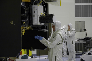
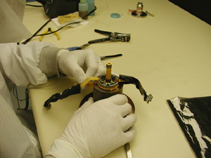 In the latter part of 2003 and early 2004, the hundreds of individual parts making up CRISM were manufactured, tested and assembled. Here a technican works on the assembly holding the IR detector. He is wearing a special suit to maintain clean conditions during instrument assembly.
5
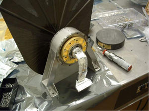
 Each subsystem, such as the optics, cooler assembly, electronics boards, and the gimbal motor and angular position encoder, was assembled separately. At left, in January 2004, is the assembled optics with the telescope baffle already mounted, being held in a jig that was used to mount and align the detectors.
6
 Here, the anti-sunward radiator is mounted in one side of the gimbal base. The metal strap is used to connect it to the spectrometer.
7
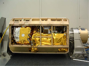
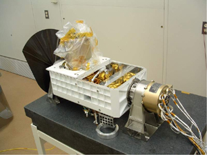 The box holding the interior components of the OSU was machined out of a solid block of aluminum and painted white to keep it cold. The optics (with the baffle removed), the radiator, and the heat pipe assembly were attached to it, and the gimbal motor and angular position encoder were added.
8
 The cooler assembly, attached to its half of the planet-facing radiator, was attached to the heat pipes before dropping it into place.
9
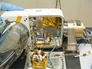
 With the coolers now in place, the yellow tube was attached to gently blow dry nitrogen into the inside of the OSU, keeping out dust and humidity.
10
 This view of the bottom of the gimbal box shows the box's interior. The "C" in CRISM is for "Compact," and that's no joke.
11
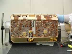 Electronics that control the detectors were mounted in the recesses in the bottom of the gimbal box. Mounting the heat-generating electronics on the outside of the box helps keep the IR detector and spectrometer cold.
12
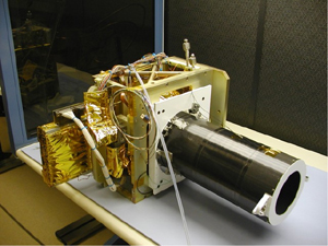
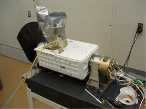
 A cover was put on the bottom of the gimbal box, the baffle was re-attached, and the DPU and GME were attached to the OSU to complete the instrument. The large metal plate was used to transport the assembled instrument and keep parts from being bumped or damaged.
13
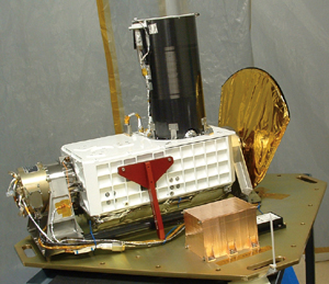
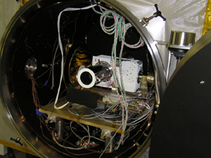 In July through September 2004, the instrument was tested extensively to verify performance of its thermal control subsystem, all of the electronics and software functions, and the quality of the data. Here CRISM is being inserted into a large vacuum chamber from which it can view light sources to calibrate the optics and detectors.
14
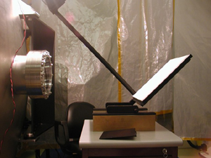 Here, a uniform brightness source was set up outside a clear window in the vacuum chamber. CRISM imaged it to test the sensitivity of the detectors.
15
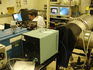 During testing, both the test facilities and CRISM itself were controlled by computers that ran carefully designed command scripts.
16
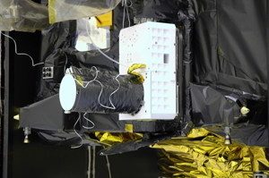
 Once CRISM's testing was completed, in September 2004 it was installed on the spacecraft. Comprehensive tests were performed to assure that both the instrument and its interface to the spacecraft were functioning as expected.
17
 By the end of February 2005, testing of CRISM was largely completed.
18
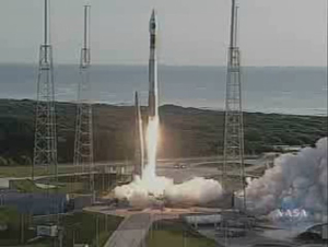 MRO's launch on August 12, 2005, ended the nearly 5-year saga of designing, building and testing CRISM.
On to Mars!